
![]()
Phone +420 541 143 246, Fax +420 541 142 224, E-mail: heatlab@fme.vutbr.cz, www.heatlab.cz
Heat Treatment
In-line heat treatment of rolled materials has become frequently used by hot rolling plants. This method achieves the required material structure without the necessity of reheating.
This text describes a design procedure of cooling sections for obtaining the demanded structure and mechanical properties. Such a procedure is typically used for the cooling of tubes, rails, long products and plates.
Cooling strategy
Specific heat treatment regimes have known results for some steels, in terms of final material structure. These tests are typically made on small samples and carried out using two cooling regimes. The first maintains constant temperature and the second maintains a constant temperature gradient. Neither of these regimes are useful in practice. Any in-line heat treatment process needs to vary the cooling intensity with time. Moreover, practice shows that results obtained using small samples are normally different from the results achieved using samples of large cross-section, even if both samples were subjected to identical temperature regimes.
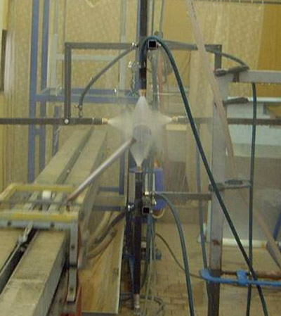
A test bench was built for the purpose of finding the optimal cooling strategy for a given steel. A steel sample embedded with thermocouples is heated to an initial start temperature in an electric furnace. The heated sample is then moved into a cooling position under the nozzle. The sample is designed so as to have one dimensional temperature field during cooling (five sides of the cube sample are insulated). A pneumatically driven deflector is placed between the hot sample and the spraying nozzle. Opening and closing of the deflector is controlled by computer. Interval timing of the opening of the deflector, the type of nozzle and feeding pressure are the parameters used to define the resulting cooling intensity. The test bench is able to cool the sample in a wide range of regimes. An example of the recorded temperatures is shown in figures below. The sample after cooling is cut, and then the hardness and structure of the cooled surface is checked to a certain depth of the sample. This cooling regime can be modified until optimal structure of the material is achieved.
Laboratory test bench for study of material structure after heat treatment
 |
 |
Example of hard cooling of a steel sample |
Example of moderate cooling |
Cooling intensity and numerical models
The verified optimal cooling strategy of the test bench must also be obtained in the rolled material. Cooling sections in the control models should achieve the demanded temperature histories in the cooled stock. In order to design a cooling section, knowledge of cooling intensity is required, both for a group of nozzles and for nozzle headers. Cooling intensity is a function of several parameters, most importantly, nozzle types, chosen pressures and flow rates, the surface temperature of a material, and velocity of material movement whilst under spray. The heat transfer test bench is implemented when distribution of heat transfer coefficients or heat fluxes must be measured. Figure below shows the result of a study of pressure levels with a group of four flat jet nozzles at a spray angle of 60° along the sample movement axis, using a nozzle pitch of 100 mm and a spray height of 100 mm , total flow rate 100 l/min at 5 bar and a sample velocity of 1 m/s. The results demonstrate the controllability of cooling intensity using variable feeding pressure.
The results gained from the heat transfer test are used in a numerical model of the temperature field in the cooled material. A virtual cooling section is created and possible temperature histories are computed. The resultant numerical model predicts the controllability of the cooling device and assists in the preparation and adjustment of fast simple control models.
Heat transfer coefficient distribution perpendicular to sample movement for four pressure levels,
position 0 is in nozzle axis
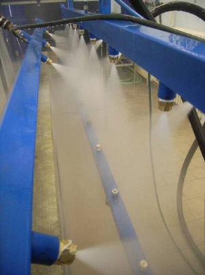
Heat transfer test of group of nozzles
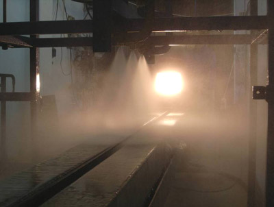
Verification at a pilot test bench
The preliminary design obtained by use of the numerical model must be then verified and fine-tuned by further full-scale cooling tests. The second laboratory test bench is designed for full-scale material samples. A piece of tube, rail, wire or plate of real dimensions is instrumented with thermocouples and the cooling is tested. The length of a laboratory test bench is limited, hence the sample must be accelerated at the test start, to a velocity normally used in a plant, and after reaching the end of its run under the cooling section, direction of movement is reversed. In this way, the sample moves several times under the cooling sections. This process of cooling is controlled to simulate running under the long cooling section used normally in the plant. Nozzles, pressures, and header configurations are tested. The design of cooling and the pressures used are modified until the demanded temperature regime is obtained. The full-scale material samples are then cut for tests of material properties and structure.
 |
 |
 |
|---|---|---|
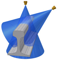
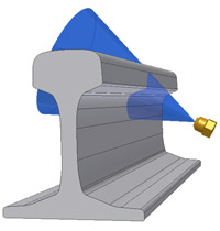
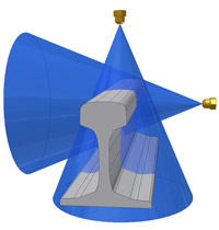
Study of nozzle positioning for rail cooling |
||
Experimental study of tube cooling
The design of cooling sections used in in-line cooling for hot rolling plants utilises laboratory measurement and numerical modelling. The first phase is in search of the best cooling regime for steels for which this is not known. The second step is to obtain a selection of technical means in order to guarantee obtaining the prescribed cooling rates. Nozzle configurations and cooling parameters are then selected and controllability of the system is checked. The final stage of the design is a laboratory test of a full size sample simulating plant cooling.
Laboratory design and measurement therefore minimises the amount of experimentation performed directly on plant thereby eliminating potential errors, whilst enabling adjustment of control models on the plant after being tested at the laboratory.
Experimental study of nozzle positioning for rail cooling
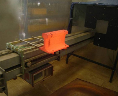
Full scale test of rail cooling – initial part of experiment
 |
 |
|---|---|
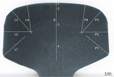
| Example of structure and hardness of rail head (horizontal axis in mm, measured from the rail surface) |
|