![]()
Phone +420 541 143 246, Fax +420 541 142 224, E-mail: heatlab@fme.vutbr.cz, www.heatlab.cz
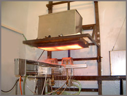
High Temperature Test Bench
The general arrangement of the experimental stand is shown in Figure 4. The basic part is a test specimen, made of an austenitic plate, size 600x320x30 mm. A set of thermocouples is embedded into a test plate and indicates temperatures at a certain depth from cooled surface. The arrangement of thermocouples is obvious from Figure 5.
Experimental procedure is done as following:
• Test plate is heated at a prescribed temperature (typically 1250oC) using an external electrical heater.
• The heater is replaced by moving trolley with nozzle. Driving system controls motion of this unit. The range of motion is from –250 mm to +250 mm.
• When the unit is moving in the positive direction, nozzle sprays the surface. Spray is reflected from surface by a deflector when nozzle is moving in the opposite direction.
• The temperature traces and nozzle position trace are logged on PC controlled data logge r.
• Experiment is finished when the test plate is cooled below a certain temperature (typically 500oC).
• The logged data are used for subsequent evaluation.
| 1 Thermocouples | 5 Nozzle |
| 2 Insulation | 6 Heater |
| 3 Test plate | 7 Defelector |
| 4 Spray | 8 Manifold |
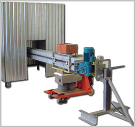
Linear High Speed Test Bench
The experimental stand was built to study the cooling of linearly, fast moving objects. The cooling of long rolled product (beams of various profiles) or the cooling of flat rolled products are typical industrial applications. The maximum speed used in the experiment depends on the mass of the tested sample. Standard tests apply speeds up to 5 m/s, tests with smaller samples can be designed for speeds up to 10 m/s. The conception with a long girder which can rotate around its longitudinal axis increases the versatility of the stand. The girder forms a guide-rail for a trolley stationing the sample. The testing position of the sample is arbitrary, i.e. the trolley can be moved on the girder and the transversal axis of the tested sample can be in an arbitrary position in relation to the horizon.
| 1 Cooling medium | 7 Moving trolley |
| 2 Pressure gauge | 8 Datalogger |
| 3 Nozzle | 9 Roller |
| 4 Moving deflector | 10 Electric motor |
| 5 Nozzle manifold | 11 Hauling wire rope |
| 6 Tested sample | 12 Girder |
The girder is divided into three two-meter-long sections. The marginal sections are used for the trolley's acceleration or deceleration. The velocity of the trolley is constant in the mid section and it is here where the measured sample is quenched by the spray nozzles. The nozzles' spray, their type and arrangement as well as the pressure of the cooling medium are also adjustable so that the experimental conditions correspond as much as possible to the real industrial ones. The tests can be carried out either for flat samples or for different profiles as shown in following figure.
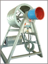
Rotating Bench
Rotating bench is designed for investigation of cooling effects on the rotating cylindrical surface. Results obtained using this bench are applicable to optimization of cooling system of rolling-mill working rolls. Parameters of stand are in accordance to this demand. Principal scheme is plotted on following figure.
| 1 Roll | 5 Nozzle |
| 2 Pressure gauge | 6 Test element |
| 3 Water supply | 7 Electric motor |
| 4 Manifold | 8 Datalogger |
Roll diameter is 650 mm, width 600 mm. A part of perimeter is equipped by element with embedded thermal sensors. Signal from sensor are connected with datalogger, rotating together with roll. Electric motor controlled by frequency inverter powered via gear box and band the roll. Speed of rotation can be change within the reach 0-5 rps.Cooling manifolds can be configured in the arbitrary position. Cooling water is supplied with pump. Experimental procedure
• Test element with thermal sensors is heated at initial temperature using an external heater.
• After temperature homogenization is heater removed and roll is turn on with prescribe velocity.
• Spraying starts.
• After spraying finish, roll is stopped and data from datalogger memory are transferred to computer for further evaluation.